
Project Overview
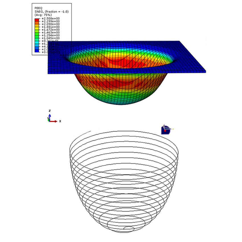
In this Abaqus project, you will learn how to generate the tool path for the Incremental Sheet Forming (ISF) process of a hemispherical part using MATLAB and Abaqus.
The main objective of this project is to define the movement of the forming tool using MATLAB and then use the generated tool-path data in Abaqus.
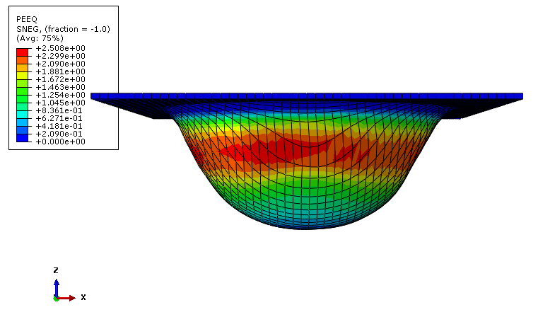
Incremental sheet forming model for the hemisphere.
Incremental Sheet Forming of a Hemisphere
In this example, the incremental sheet forming process is performed to produce a hemispherical shape. The forming tool moves progressively over the sheet and gradually creates the desired geometry.
The tool follows a spiral path during the forming process. This continuous movement allows the sheet to be formed gradually.
Spiral Tool Path
The tool moves along a spiral trajectory during the incremental forming process. The spiral path is generated using MATLAB and is then used to define the tool movement in Abaqus.
The generated path contains the coordinates required to control the position of the forming tool during the simulation.
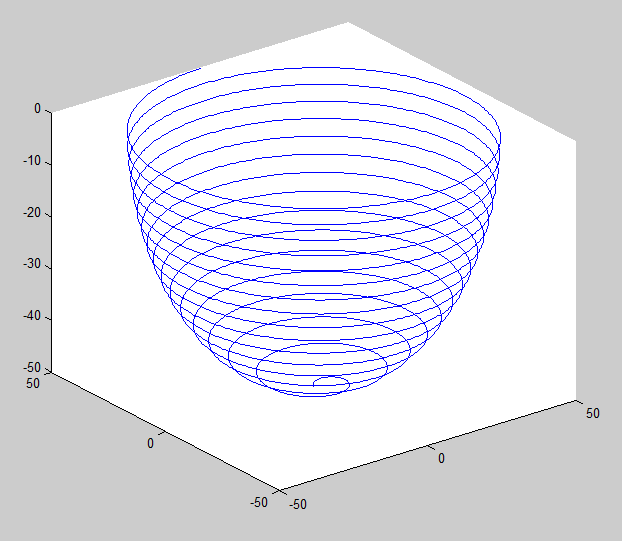
Spiral tool path generated using MATLAB.
Hemisphere Geometry
The geometry considered in this project is a hemisphere. The diameter of the hemisphere is 100 mm.
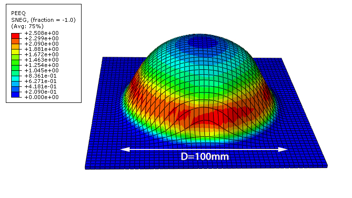
Diameter of the hemisphere used in the model.
Generating the Tool Path Using MATLAB
MATLAB is used to generate the movement of the forming tool along the spiral path. The procedure consists of several steps that are explained in the tutorial.
Step 1 – Define the Time Period
In the first step, the time period of the tool movement is defined using MATLAB. In this example, the total time period is 800 seconds.
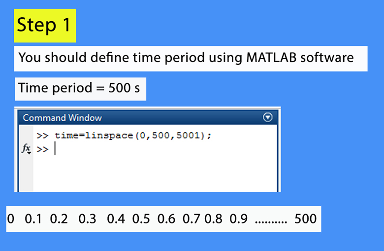
Defining the time period of the tool movement in MATLAB.
Step 2 – Export MATLAB Data to Excel
After generating the required tool-path data in MATLAB, the data is exported to Excel. The Excel data is then used to define the tool movement in Abaqus.
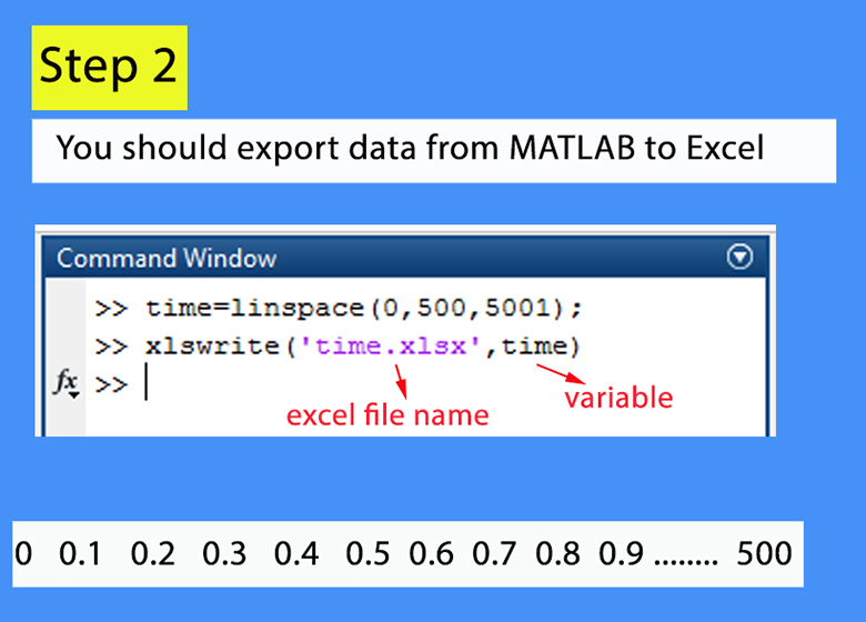
Exporting the generated tool-path data from MATLAB to Excel.
Step 3 – Define the Tool Movement
The generated coordinates are used to define the movement of the forming tool. The tool follows the generated spiral path during the Abaqus simulation.
The remaining steps required to generate and implement the complete tool path are explained in the full step-by-step training video.
Tool Path Data
The tool-path coordinates are provided in Excel files and include the X, Y, and Z amplitude data required for defining the tool movement in Abaqus.
What You Will Learn
- How to model incremental sheet forming of a hemisphere in Abaqus.
- How to generate a spiral tool path.
- How to generate tool-path data using MATLAB.
- How to define the time period of the tool movement in MATLAB.
- How to export MATLAB data to Excel.
- How to generate X, Y, and Z tool-path data.
- How to use amplitude data to define tool movement in Abaqus.
- How to define a moving forming tool in Abaqus.
- How to simulate incremental sheet forming of a hemisphere.
Key Features
- Incremental Sheet Forming (ISF) simulation.
- Hemisphere forming.
- Spiral tool path.
- MATLAB-based tool-path generation.
- Excel-based X, Y, and Z amplitude data.
- Tool movement defined in Abaqus.
- Time period of 800 seconds.
- MATLAB file.
- Excel tool-path files.
- Excel material file.
- Abaqus CAE file.
- Abaqus INP file.
- Step-by-step training video.
Project Information
Important information about this project
Payment & Support
Need help with your purchase?
Secure Payment
Your payment is processed securely through our online payment system.
Need Help?
If you have any questions about this product, please contact us by email.
saeedofmoeini@gmail.com
Hicham
I need this project.
Admin
You can buy it by credit card